
取消
We have seen previously that a DC series circuit has a common current flowing through it, and that a DC parallel circuit has a common voltage across it. But what happens when we have combination series and parallel circuits. How can we solve these series-parallel combination circuits to find the individual current and voltage drops around it.
Thus, when analysing combination circuits, we can use different circuit analysis laws for series and parallel circuits to produce a much simpler equivalent circuit between any two points (or terminals). Allowing us to solve and find the unknown values of voltage, current, and resistance around the circuit.
But first let us remind ourselves of the characteristics of a DC Series Circuit and a DC Parallel Circuit.
DC Series Circuit
The equivalent or total resistance (RT) of a series circuit equals the sum of the individual resistances. Since there is only one closed path or loop for electric current to flow around,
the total current (IT) supplied by the voltage source (VS) will therefore have the same magnitude flowing through each series connected resistance as shown.
DC Series Circuit
dc series circuit
Note also that for a “series string” of pure resistances, the sum of the voltage drops across each resistance equals the source voltage, VS. Thus, a series connected circuit provides voltage division.
DC Parallel Circuit
Parallel circuits have two or more components connected across the same voltage source. That is the source or applied voltage appears across all circuit elements. Each parallel path is called a “branch” and will have its own individual current as shown.
DC Parallel Circuit
dc parallel circuit
Combination Series and Parallel Circuits
A series–parallel circuit is one which is made up of both series and parallel circuits in combination. The possible number of combinations is endless and as such no two circuits will be the same so therefore, they must be treated and solved individually.
Any combination of series and parallel circuits can be solved by simplification. By repeatedly replacing any series and parallel combinations of circuit elements by their equivalent. For example, a number of resistors, which are in series or in parallel, can be replaced by one single resistor which will have the same effect on the circuit.
So let’s start with the following series-parallel combination circuit.
Combination Series and Parallel Circuit
combination series and parallel circuits
Hopefully we can see that resistors R2 and R3 in the above circuit are connected together in series. Thus RS (R-series) equals:
RS = R2 + R3 = 28Ω + 12Ω = 40Ω’s
Combining the two series resistors R2 and R3 into one single resistance, RS of 40Ω’s. Now each branch has only one resistor so we can redraw the circuit as follows:
Series and Parallel Combination Circuit
Ok, now we should be able to see that resistors RS and R4 are connected together in parallel. Since we have a simple parallel circuit of different values, we can use the reciprocal rule to find the equivalent resistance, REQ of the two parallel branches as follows:
equivalent resistance
Thus combining the two parallel branch resistors RS and R4 into one single equivalent resistance, REQ of 8Ω’s. The resultant resistive circuit will now look something like this:
series resistors
We can see that the two remaining resistances, R1 and REQ are connected together in a series combination. So they can be summed (added) together (resistors in series) so that the total circuit resistance, RT seen by the voltage source, VS is given as:
RT = R1 + REQ = 12Ω + 8Ω = 20Ω’s
Thus a single equivalent resistor of just 20Ω’s can be used to replace the four resistors connected together in the original combination series and parallel circuits above.
By using Ohm’s Law, the value of the total current, IT flowing out of the voltage source and around the circuit can be calculated as:
Circuit Current
combination series parallel circuit current
The voltage drop across resistor R1 and voltage value at node VA.
voltage drop resistor R1
Thus the voltage magnitude at node VA is found to be 40 volts. This voltage value of 40 volts is also the applied voltage across the parallel combination of (R2 + R3) || R4. Therefore, the current flowing through the R4 resistor branch can be calculated as:
current through resistor R4
Since the total current IT is equal to the sum of the two branch currents I1 + I2, it therefore follows that the current flowing through the first parallel branch consisting of resistors R2 and R3 must be equal to:
I1 = IT – I2 = 5 – 4 = 1 Ampere
With a current of 1 ampere flowing through resistors R2 and also R3 (series elements), the voltage drops across these two series connected resistors is calculated as:
VR2 = I1 x R2 = 1 x 28 = 28 volts
VR3 = I1 x R3 = 1 x 12 = 12 volts
To double check our calculations for the voltage level at VA
VA = VR2 + VR3 = 28 + 12 = 40 volts, and is correct.
The above combination series and parallel circuits example above is redrawn with the calculated currents and voltages inserted.
Final Combination Series and Parallel Circuits
final combination series and parallel circuits
We could if so wished, also calculate the total power consumed, PT or the power dissipated by the individual components around the circuit since electric power, P equals:
P = V*I, P = I2R, and P = V2/R
Then using our known values of VS = 100V, IT = 5A, and REQ = 20Ω’s. The total power consumed by the combination series and parallel circuits is calculated as:
PT = VS*IT = 100*5 = 500 watts
Thus the power dissipated by each resistor is:
PR1 = 300W, PR2 = 28W, PR3 = 12W, and PR4 = 160W
Again to double check:
PT = PR1 + PR2 + PR3 + PR4 = 300 + 28 + 12 + 160 = 500 watts
Now let us try a second example with a more complex series-parallel combinations of resistive elements.
Series-parallel Combination Circuit
combination series and parallel circuit two
1. Equivalent Resistance, REQ:
Resistors R6 and R7 are connected in a parallel combination for the equivalent resistance called, R10
combination series and parallel circuit resistance
Resistances R5 and R10 now in series are added for equivalent resistance, R11
R11 = R5 + R10 = 68 + 72 = 140Ω’s
Branch resistances R2, R3 and R4 are connected in series, so are added for equivalent resistance, R12
R12 = R2 + R3 + R4 = 75 + 125 + 150 = 350Ω’s
Resistances R11 and R12 are in a parallel combination for the equivalent called R13
parallel circuit equivalent resistance
Finally, resistances R1, R13 and R8 now all connected in series and therefore are added together for a final equivalent resistance, REQ of:
REQ = R1 + R13 + R8 = 100 + 100 + 40 = 240Ω’s
2. Total Supply Current, IT:
total supply current
3. Voltage at Node A
VA = VS – (IT x R1) = 120 – (0.5 x 100) = 70 volts
Note the voltage at node VB equals the voltage level at node VA since it is a point at which they are joined. That is VB = VA.
4. Branch Current, I1
parallel branch current I1
5. Branch Current, I2
parallel branch current I2
6. Combination Series and Parallel Circuits Voltage Drops All Resistors
combination series and parallel circuits voltage drops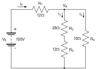
Again, if we so wished, we calculate the total power PT consumed (60 watts), and the power dissipated around the circuit by the individual resistances.
Combination Series and Parallel Circuits Summary
We have seen here that DC combination series and parallel circuits are nothing more than an assortment of series circuits with parallel circuits in various combinations. Series-parallel combination circuits make it possible to combine the voltage division characteristics of series circuits with the current division characteristics of parallel circuits.
The main characteristics of combination series and parallel circuits are defined as being:
■ Current Flow: – In the series parts the current is the same through all the components within the series string. In the parallel parts the total current is the sum of the currents divided among the different parallel branches.
■ Voltage Distribution: – In the series parts the voltage drops across each component is different creating voltage division. The total voltage is the sum of the individual voltage drops.
In the parallel parts the voltage across all parallel connected branches is the same and each parallel branch receives the same voltage level.
■ Equivalent Resistance: – In the series parts the total resistance is the sum of all individual resistances in the series part of the circuit. The total resistance value is greater than the largest series resistance.
In the parallel parts the reciprocal value of the total resistance is equal to the sum of the reciprocals of the branch resistances. The total resistance is less than the smallest individual resistance.
■ Power Distribution: – Power dissipation around a series-parallel circuit can be calculated using the standard P = I2R, P = V2/R, or P = V*I, formulas depending on which two quantities are known.
In the series parts power dissipation depends on the current. In the parallel parts power dissipation depends on the voltage.
Simplifying Combination Series and Parallel Circuits
Understanding and analysing combination series-parallel circuits typically involves breaking them into simpler series or parallel parts to calculate total resistance, voltage drops, and current distribution as solving combination circuits is generally easier if the circuit is reduced to simpler circuits.
Determining the equivalent resistance of a series-parallel circuit requires a logical step-by-step approach allowing us to find the voltage drops across, and the current through, each component.
The first step is to identify the purely series and parallel sections and then breaking the circuit down into simpler parts by reducing either the series or parallel combinations one at a time.
It is always good practice to verify your answers by checking that the sum of individual voltage drops across series components equals the total applied voltage, (voltage divider) and that the sum of the currents in the parallel branches equals the total current supplied to the parallel branches, (current divider). By following a systematic reduce and return approach, you will be able to solve any combination of series-parallel DC circuits.